Wiring two amplifiers together effectively requires distributing power, managing signal input, and safely handling the speaker outputs. Follow these steps carefully.
Step 1: Preparation & Components
- Amplifiers: Choose amps compatible with your goal (more power to a single sub, powering different speakers, etc.).
- Head Unit: Your source unit with RCA preamp outputs (likely needing 2 pairs).
- Power Wire: Sufficient gauge (e.g., 4 AWG or 0 AWG) from battery to distribution block.
- Ground Wires: Short, heavy gauge wires to a clean chassis point for each amp.
- Distribution Block: One for Power (fused near battery), one for Ground (optional but recommended).
- Fuses: Main fuse near battery + fuses in distribution block.
- Remote Turn-On Wire: Single wire from head unit's remote output.
- RCA Cables: Two pairs (for two channels each) from head unit to amps. May need Y-splitters.
- Speaker Wire: Appropriately sized for your speakers/subwoofers.
Step 2: Wiring Power & Ground
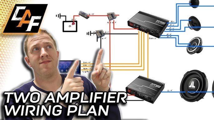
Diagram Component: Battery -> Fuse Holder -> Power Distribution Block -> Amps
- Connect thick Main Power Wire from battery positive (+) to a fuse holder (within 18 inches of battery), then to the input of the Power Distribution Block.
- Run individual Power Wires (correct gauge for each amp's current draw) from the distribution block outputs to each amplifier's +12V terminal.
- Connect a Ground Wire from each amplifier's GND terminal directly to a clean, bare metal point on the vehicle chassis. Use star washers. Keep these wires short.
- Optional: Use a Ground Distribution Block near the amps if multiple ground points are impractical.
WARNING: Fuses are critical for fire prevention. Never skip them.
Step 3: Remote Turn-On & Signal Connection
Diagram Component: HU Remote -> Amps REM
- Run a single small gauge (e.g., 16-18 AWG) Remote Turn-On Wire from the head unit's Remote or Antenna Remote output.
- Connect this wire to the REM terminal on Amplifier #1.
- Run a short jumper wire from Amplifier #1's REM terminal to the REM terminal on Amplifier #2.
Diagram Component: HU RCA Outs -> Y-Splitters? -> Amps RCA Ins
- Connect one pair of RCA cables from the head unit's rear RCA outputs (e.g., Front/Rear or Sub/Non-Sub) to the input of the primary amplifier handling those channels.
- If the head unit only has one pair of RCA outputs, connect them to a 2-Female to 1-Male RCA Y-Splitter cable for each channel.
- Run a second set of RCA cables from the Y-splitter outputs (or the head unit's second RCA pair) to the input of the second amplifier.
Step 4: Speaker Output Wiring
- Connect Speaker Wires from each amplifier's Speaker Outputs (+/-) directly to their respective speakers or subwoofers.
- Do NOT connect the speaker outputs of the two amplifiers together. Each amp drives its own speaker load independently.
- Match impedance: Ensure the speaker(s) connected to each amp present a load within that amp's stable operating range (e.g., 4 Ohms, 2 Ohms).
Step 5: Final Check & Power-On
- Double-check all connections: Ensure no loose strands, positive and negative are correct, grounds are solid, fuses are installed.
- Verify no power/ground shorts: Before connecting the battery, use a multimeter to check for continuity between the main power wire near the battery and ground (should be none).
- Reconnect battery terminal.
- Turn on the head unit. Both amplifiers should power on (indicator lights).
- Set amplifier gains: Set initial levels very low and carefully adjust using a test tone and multimeter/DMM or oscilloscope for clean output. Do not set by ear.
This configuration provides a reliable and safe method to power multiple amplifiers simultaneously.