Installing a power inverter in your truck provides convenient AC power. Follow these professional steps for a safe and reliable installation.
Planning & Safety First
Choose Location: Select a well-ventilated, dry area away from engine heat and driver/passenger limbs. Common spots: under a seat or securely mounted to cab wall/corner.
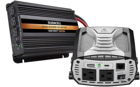
Determine Power Needs: Calculate the wattage of devices you'll run simultaneously. Size your inverter accordingly (e.g., 1500W, 3000W). Consider Pure Sine Wave inverters for sensitive electronics.
Circuit Protection: The inverter must have appropriately sized fuse protection within 18 inches of the battery terminal.
Disconnect Power: Always disconnect the truck's negative battery terminal before starting.
Essential Tools & Materials
- Chosen Inverter
- Proper Gauge Wire (See chart below)
- ANL or Mega Fuse & Holder (Rated for inverter's max current)
- High-Amperage Terminal Lugs (Copper, properly sized for wire and inverter terminals)
- Crimping Tool
- Wire Cutters/Strippers
- Heat Gun & Marine-Grade Shrink Tubing
- Wire Loom/Conduit
- Wrenches & Socket Set
- Mounting Hardware (Bolts, Brackets, Lock Washers)
- Grounding Cable & Point
Wire Gauge Guide
- 1000W or less: AWG #6 (Minimum)
- 1000W - 1500W: AWG #4
- 1500W - 3000W: AWG #1/0 or AWG #2/0
- Consult manual: Always follow the inverter manufacturer's specified wire gauge.
Installation Steps
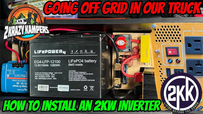
1. Mount the Inverter: Securely fasten using provided brackets/screws. Ensure no contact with metal surfaces unless specified (some require insulated mounting). Drill mounting holes carefully.
2. Run Positive Cable:
- Route heavy-gauge positive cable from battery's positive terminal to the fuse holder location near the battery.
- Install the fuse holder onto the cable end near the battery and connect it securely to the positive terminal. Do NOT insert fuse yet.
- Continue routing the cable securely through the firewall/cable gland to the inverter location, protecting it from abrasion.
- Crimp terminal lug onto inverter end, heat shrink, and connect to inverter's positive (+) terminal. Tighten securely.
3. Run Ground Cable:

- Cut heavy-gauge cable to length (keep it short).
- Crimp terminal lugs on both ends.
- Securely attach one end to the inverter's negative (-) terminal.
- Attach the other end to a dedicated, clean, unpainted metal point on the truck's frame/chassis near the inverter. Scrape paint for metal contact. Secure bolt tightly.
4. Secure Wiring: Bundle and secure all wiring using wire loom/conduit and tie wraps, preventing contact with moving parts or heat sources.
5. Final Connection & Fuse Insertion: Double-check all connections are tight and correct. Reconnect the truck's negative battery terminal. Finally, insert the main fuse into the holder near the battery.
6. Ground the Inverter Chassis: Connect a separate AWG #10-12 wire from a designated ground screw on the inverter chassis to the same frame point used for the main ground.
Testing
- Turn on the truck's ignition to accessory/run position.
- Power on the inverter. A green light typically indicates normal operation.
- Test with a small, low-power AC device (e.g., phone charger, lamp).
- Gradually test higher loads if applicable. Ensure no abnormal heat on connections or cables.
Critical Considerations
- Voltage Drop: Use the thickest cable recommended for your inverter/distance.
- Battery Drain: Running high-power appliances with the engine off will deplete the starter battery quickly. Use deeply-cycle batteries for prolonged stationary use.
- Heat Management: Ensure adequate inverter ventilation. Do not cover vents or block airflow.
- Inverter Lifespan: Avoid sustained operation near its maximum rated wattage.